Thin-layer clarifiers, thickeners
Hydromechanical processes of separation of heterogeneous systems in the gravitational field of the Earth are widely observed in nature and are widely used in technology, being implemented in devices that, depending on their technological purpose, are referred to as sedimentation tanks, thickeners or to various sorts of classifiers.
In large-scale industries, these capacitive, large-sized devices are considered as building systems. There are horizontal, vertical, radial and other sedimentation tanks.
The use of cassettes with thin-layer elements in sedimentation tanks intensifies the process of separation of heterogeneous systems up to 10 times, which, during the reconstruction of existing facilities, can significantly improve the qualitative and quantitative indicators of their work.
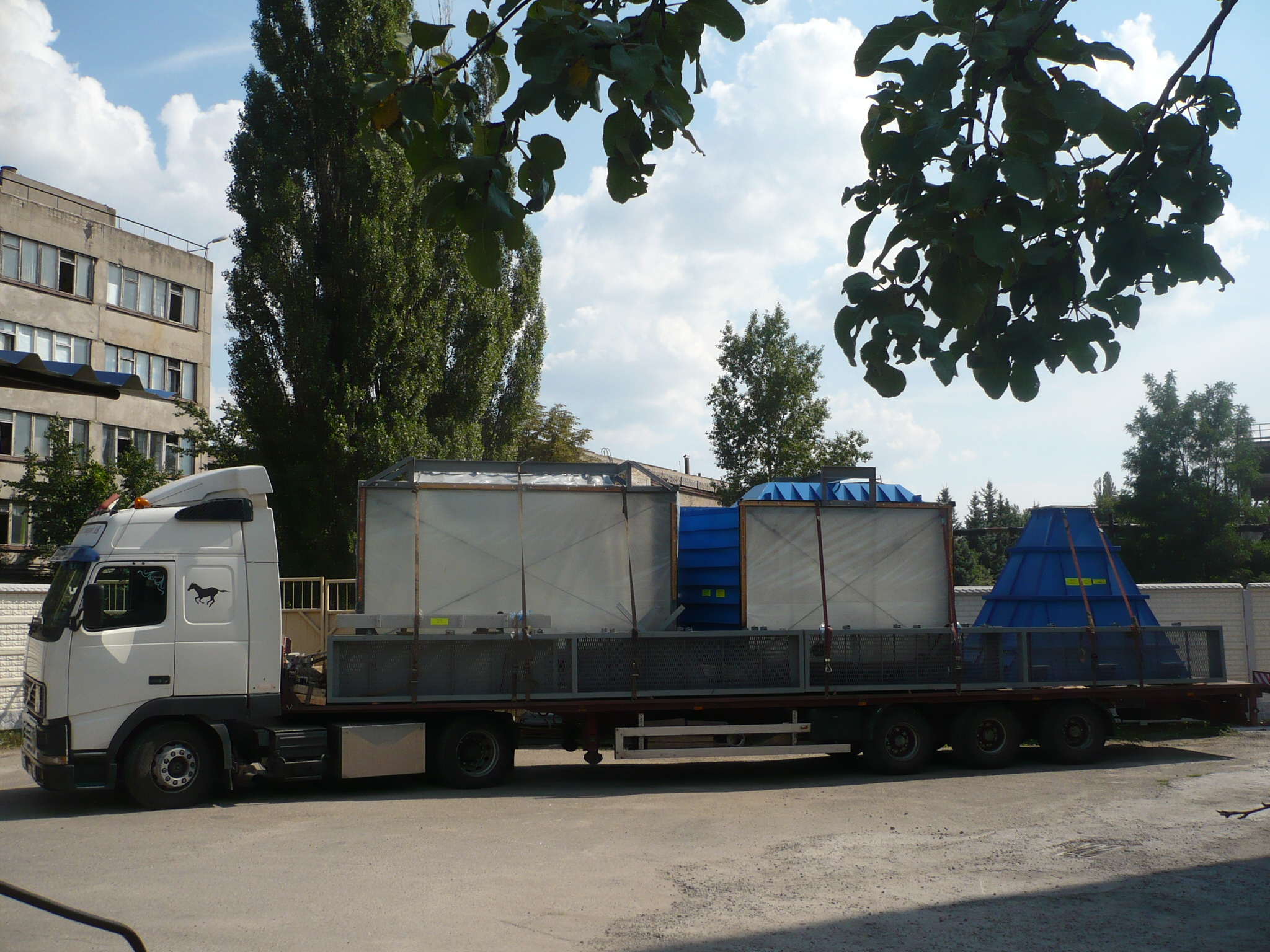
High-performance sedimentation tanks, thickeners with thin-layer cassettes have small dimensions, which allows them to be completely manufactured at the factory and delivered to the site by road as ready-made units for SKD on site.
The supply of thin-layer sedimentation tanks, thickeners in the form of finished devices significantly reduces the volume of design and construction work.
 |
 |
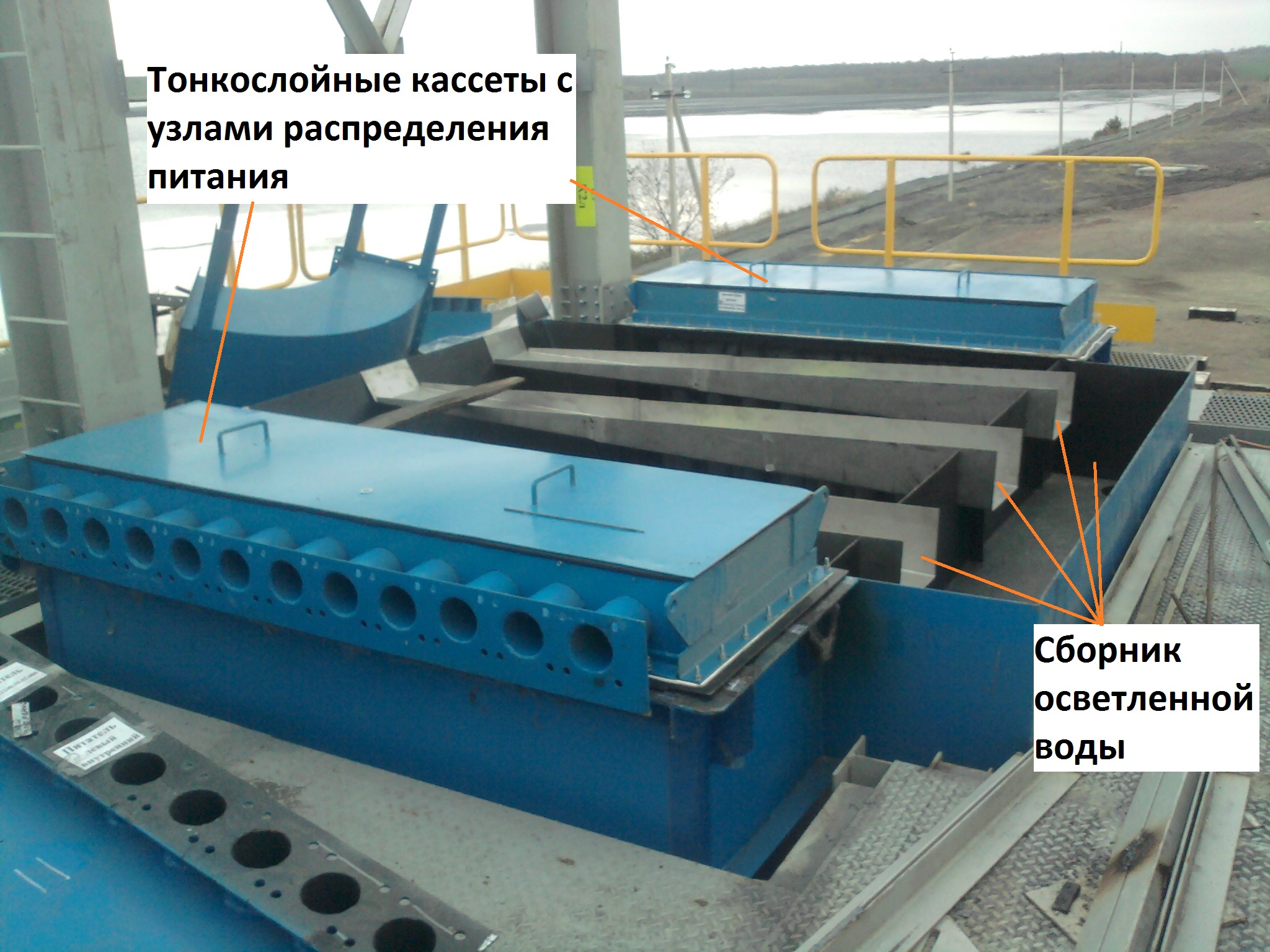 |
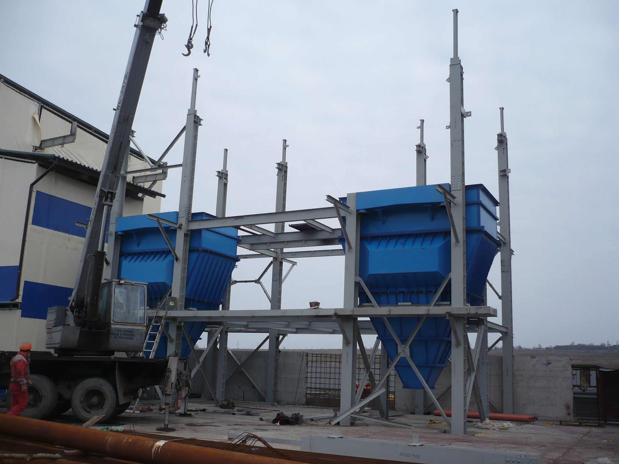
| Sump delivery by road | Installation of 2 sedimentation tanks | Top view of the thin-layer clarifier |
The device of a vertical thin-layer settler (thickener) for separating the pulp, pretreated with a flocculant.
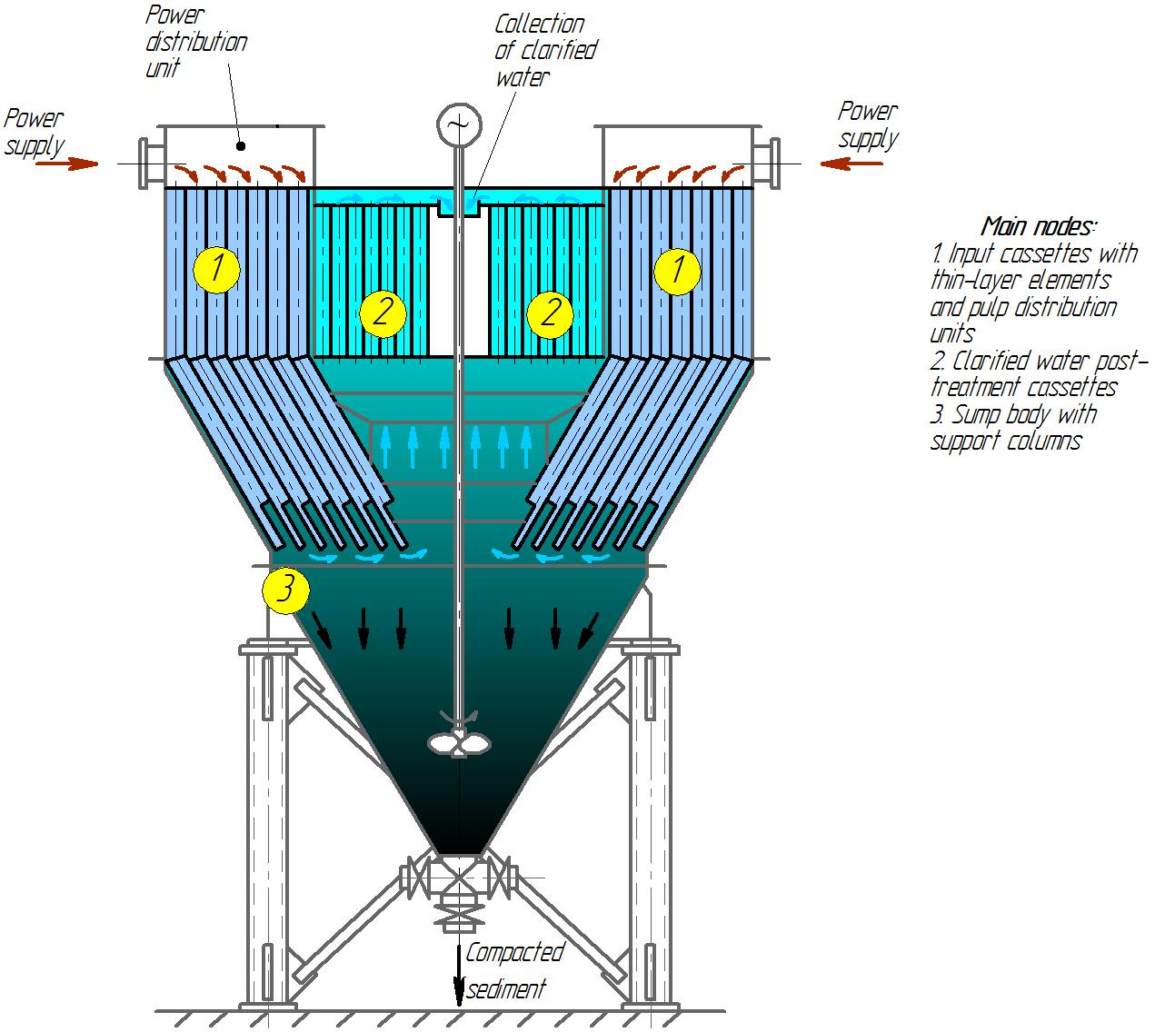
Рис. 1.Diagram of a once-through-countercurrent thin-layer clarifier type Ecomash VTS (Vertical thin-layer sump).
During the operation of the sump, slurry enters the inlet cassettes with thin-layer elements. Pulp is understood as the mixture of solid particles and liquid in which they are suspended. According to the particle size, pulps are distinguished: coarse suspensions, thin suspensions, sludge (sludge). The pulps fed to the settling tank can be conditioned by the addition of coagulants or flocculants.
To organize a uniform supply of power to the thin-layer elements, the input cassettes are equipped with power distribution units.
The direction of movement of the clarified liquid and condensed in the thin-layer elements of the input cassettes coincide, i.e. currents straight-through, descending . Such designs are preferred for slurries with a relatively high solids concentration.
Further, the sludge of the cassettes enters the pyramidal bottom of the sump, where sludge compaction takes place. Sludge compaction is intensified by stirring with a stirrer.
The discharge of sludge from the settler (thickener) can be continuous or periodic , which is determined by technological objectives and material balance.
Clarified water rises through a post-treatment cassette with thin-layer elements, in which the movement of the additional purified liquid is ascending , the direction of the clarified water and thickened are opposite , i.e. current countercurrent .
Lightened water is collected in a tray and then, through the collection of clarified water of the sump, it is removed by gravity into the external network.
Thin Layer Sump SpecificationsEcomash VTS
| № п/п | Parameter name | The values |
| 1. | Volumetric performance,max, м3/hour:
-slurry with a flocculant, such as slime water from coal preparation, waste water from rolling mills with a sedimentation rate of suspended solids of 4 mm / s; -pulp without chemical additives with a sedimentation rate of suspended solids of 1 mm / s. |
270
30 |
| 2. | Mass productivity (productivity for solid feed), max, t / h: | 15 |
| 3. | Clarification efficiency η =(Сп -Сосв)/Сп , max, %
– пульпа с флокулянтом |
99 |
| 4. | Overall dimensions, no more, mm:
Length Height Width |
4255
6800 3110 |
| 5. | Sump volume, m3 | 27 |
| 6. | Масса сухого отстойника, кг, не более | 9200 |
The main unit of a thin-layer clarifier is cassettes with thin-layer elements formed by parallel plates or tubular channels, which allow developing a sedimentation surface of the settler and organize optimal hydrodynamic conditions for separating heterogeneous systems.
 |
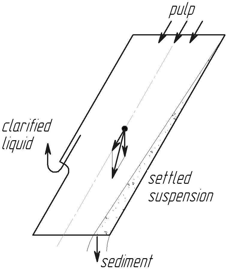 |
| Upward flow direction of the slurry in the thin layer element | Downward flow direction of the slurry in the thin layer element |
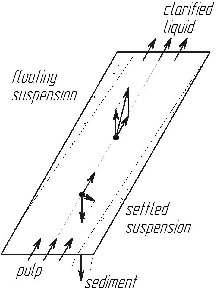
Fig. 2. Scheme of separation of a heterogeneous system in a thin-layer cassette element.
The floating suspension moves with the clarified pulp liquid upward along the upper wall of the canal. The floating suspension is collected outside the thin-layer element in the upper part of the settler (flotation device) and is separated from the clarified liquid.
The settling slurry collects on the lower wall of the channel and slides down the channel, forming a thickened sediment sludge.
The slope of the thin-layer element is determined primarily by the friction of the thickened sediment against the element material and is ≈50..60 ° for a self-cleaning thin-layer element.
The length of the thin-layer element and the flow rate of the pulp through it are selected in such a way that the processes of separation of the pulp are completed at the exit from the element.
The shape of cassettes with thin-layer elements in the plan can be square, rectangular or segmented to maximize the filling of the internal space of the sump.
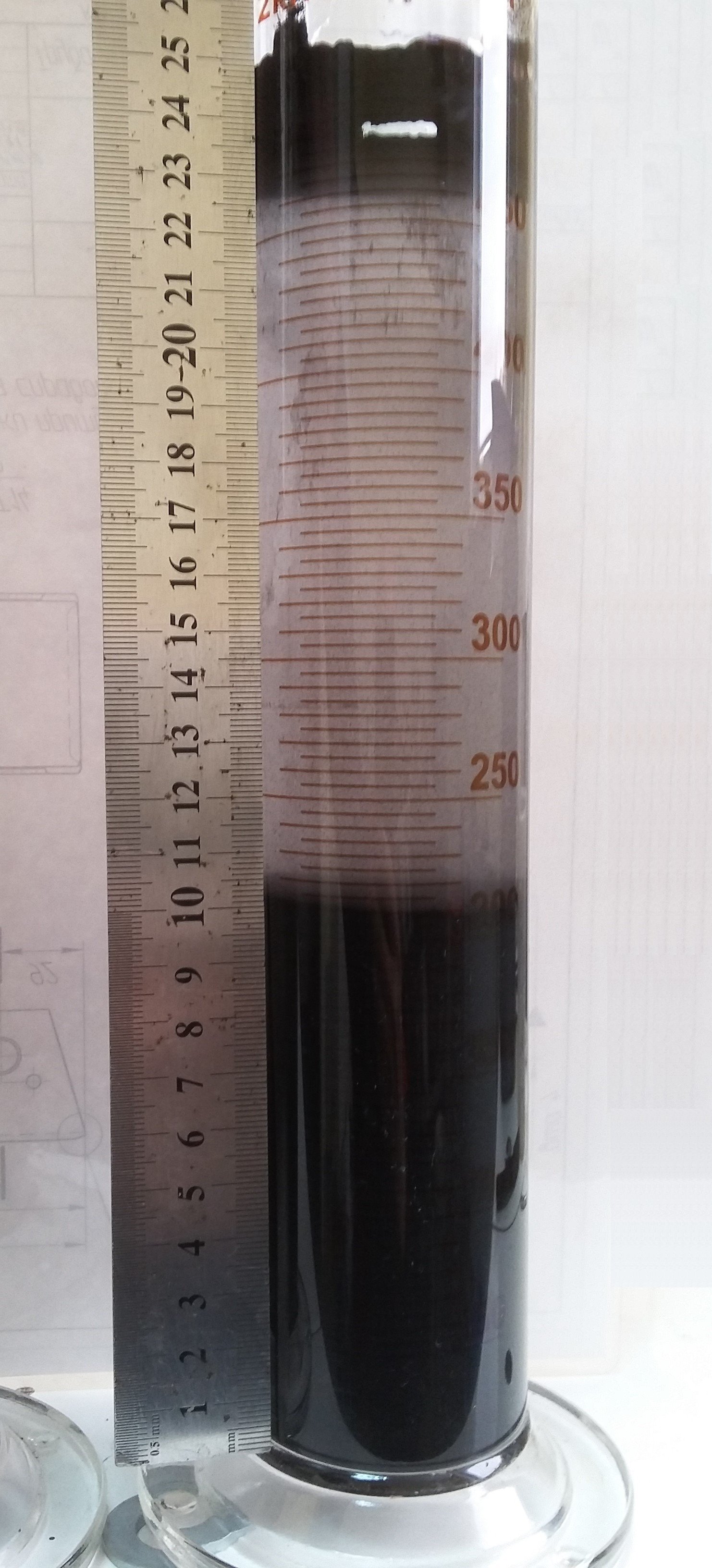
The initial data for the selection of a settler (thickener) and the selection of thin-layer cassettes are the results of a laboratory analysis of the pulp . The results of slurry separation are determined by the laws of sedimentation or floating of suspended solids in a liquid and are illustrated below:
 |
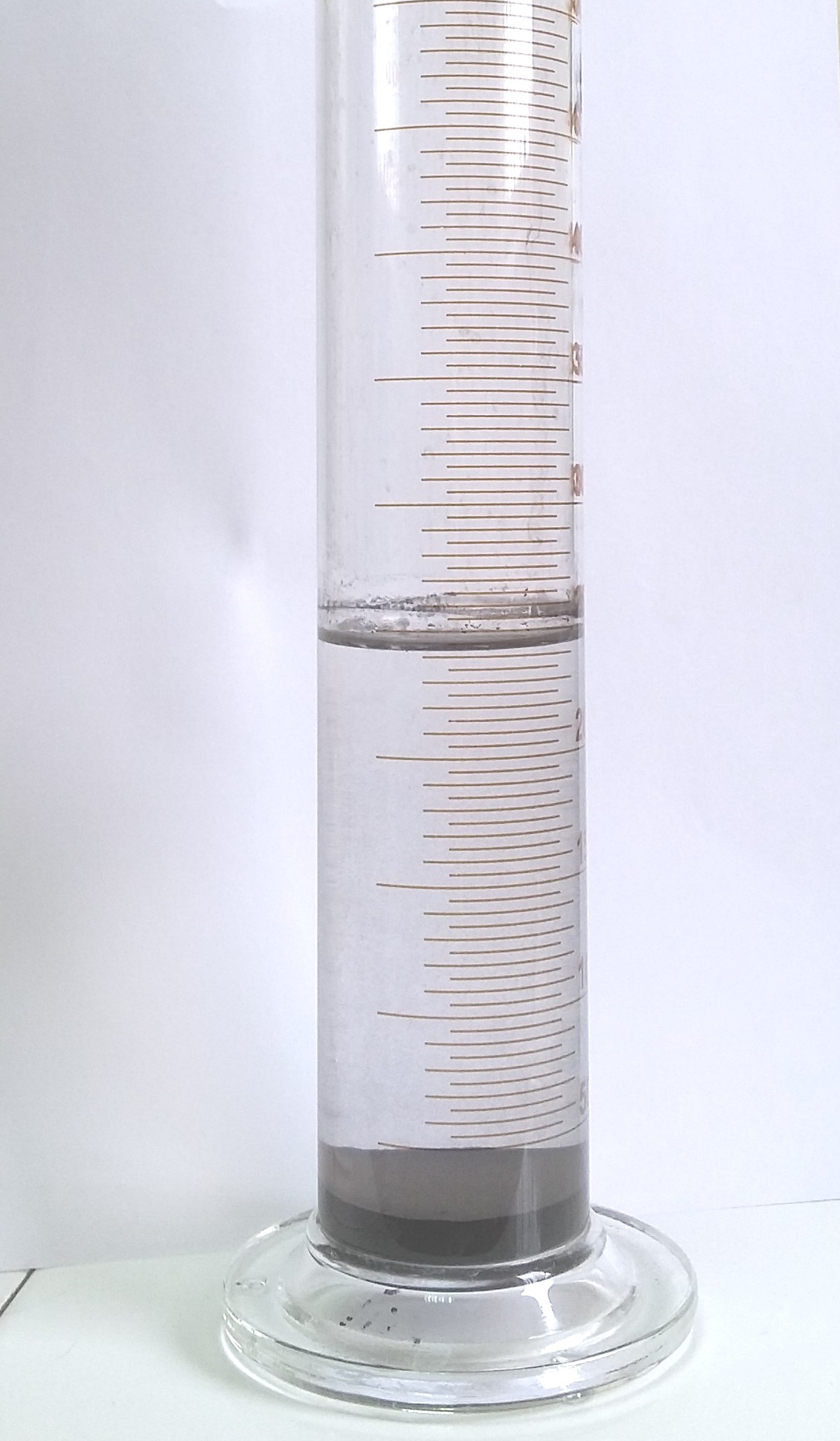 |
| Separation of the pulp into floating suspension, clarified liquid and thickened sludge | Separation of the pulp into clarified liquid and thickened sludge |
The results of the operation of thin-layer sedimentation tanks as part of the Sludge Water Treatment and Waste Dewatering Module are shown below.